C-5610 Touch Kiosk V2 Motherboard Installation (Existing)
Requirements
- TK2 Motherboard assembly
- TK2 Motherboard retrofit kit
Instructions
NOTE: You will need to retain the original motherboard for any parts that may not be included.
Power off the Kiosk and unplug the power before proceeding.
NEVER PULL ON WIRES! Always remove connectors by the plug.
Existing Motherboard Removal
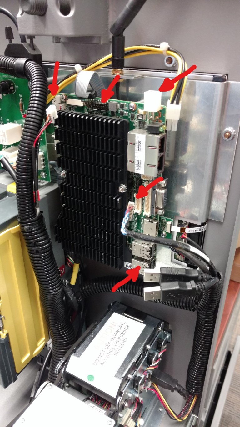
Unplug all existing cables from the current mother board including:
- USB Cables
- Video Power Cable
- Power Control Board interface cable
- Video cable
- Power Connection
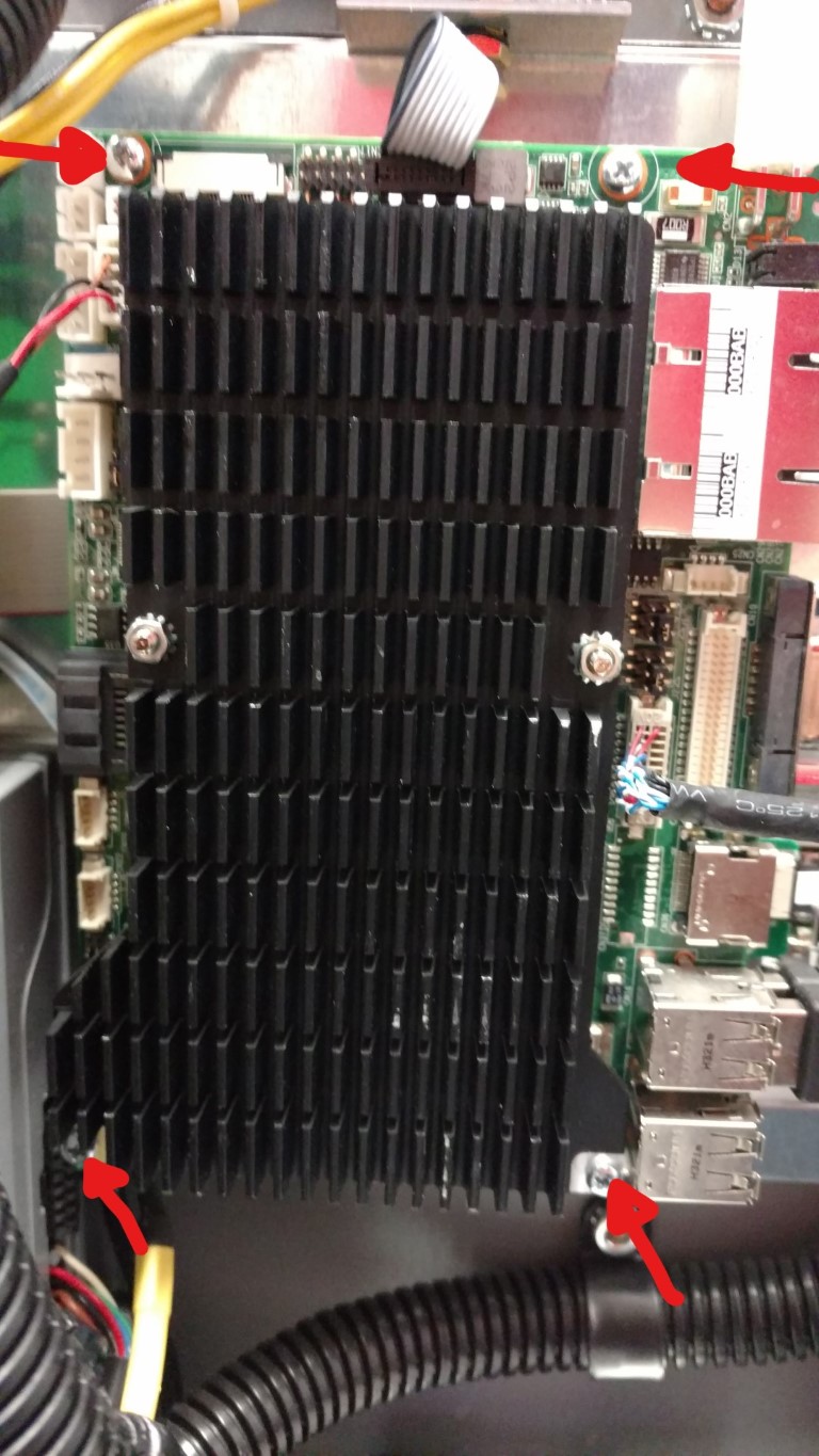
Remove 4 Mounting screws as indicated:
Carefully pull the board from the machine making sure to stop and remove the gray serial cable and the antenna cable from the wireless card on the back of the board taking care not to damage the connectors.
Move the grey Power Control Board cable to the left out of the way, as it will plug into a different spot.
If wireless card is to be reused:
Remove the wireless card from the existing motherboard by unscrewing the (2) micro screws from the board. Lift up on the card and pull out of the socket.
Insert the wireless card into the new motherboard and secure with the same micro screws you removed from the original board.
Installing the new Motherboard (C-5671-ASSEM & K-5671 mounting kit)
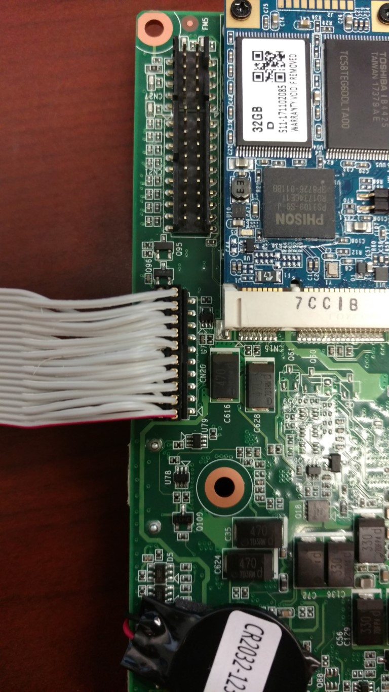
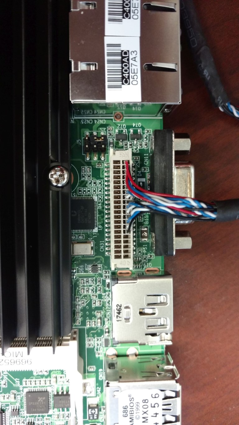
Insert the gray serial cable into the slot marked CN20. Please make note of the pink wire and its orientation in the slot:
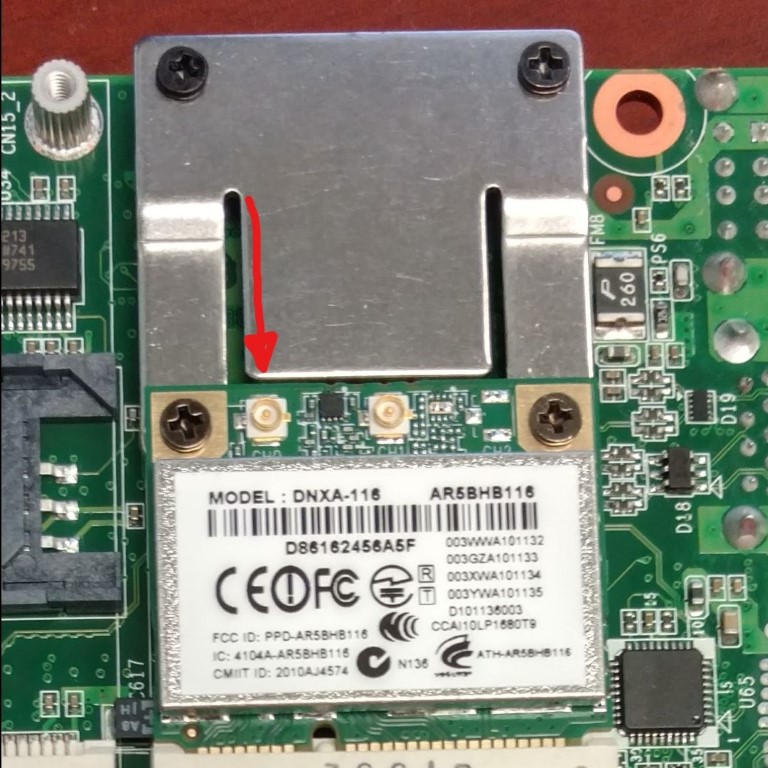
Carefully insert the antenna cable into the wireless card on the connector marked CH0. DO NOT force the connector. It should snap into the port with minimal force.
Insert the longer screws into the top holes in the motherboard assembly and slide on the nylon spacers:
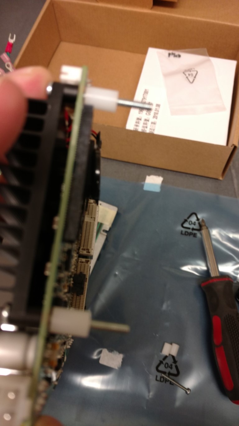
Insert the screws into the mounting plate on the Kiosk and tighten slightly to keep from falling out.
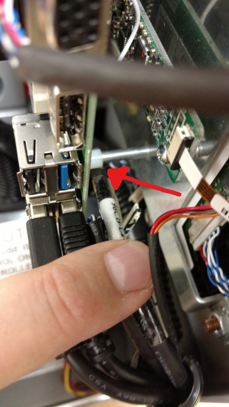
Insert the shorter screws in the bottom of the motherboard and slide the white nylon spacers on the screws and secure into the existing posts.
You may want to have a pair of needle nose pliers to make this part easier. Hold the spacer and slide screw into it and into the standoff.
Hand tighten all screws. Do not over tighten!
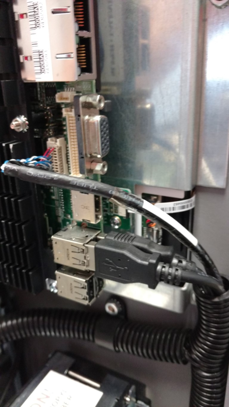
Plug USB Cables into the USB ports.
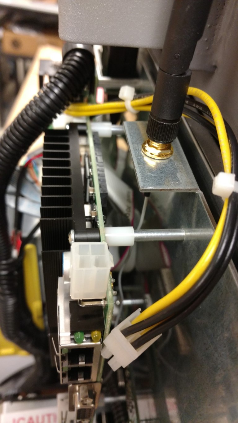
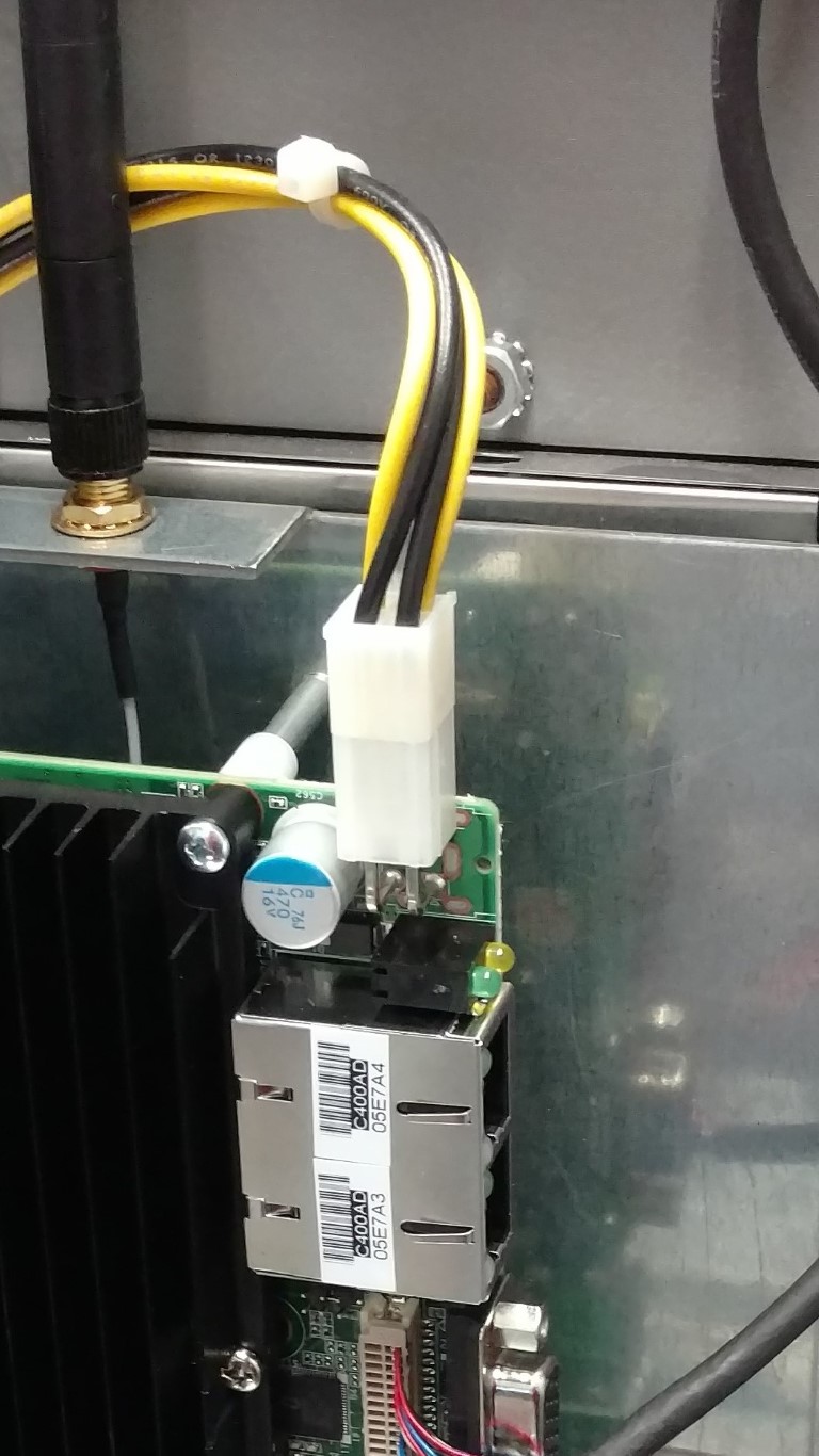
Plug in the yellow/black power connector to the top of the board.
Plug in replacement video cable taking care not to force or bend pins on the connector. Do Not use existing cable.
Connect other end of video cable into the monitor. USE extreme caution inserting the connector as the pins are fragile and will bend easily. Slide the connector straight in to the port. Do not angle the connector.
The connector has a silver plate that should match up with the connector on the monitor.
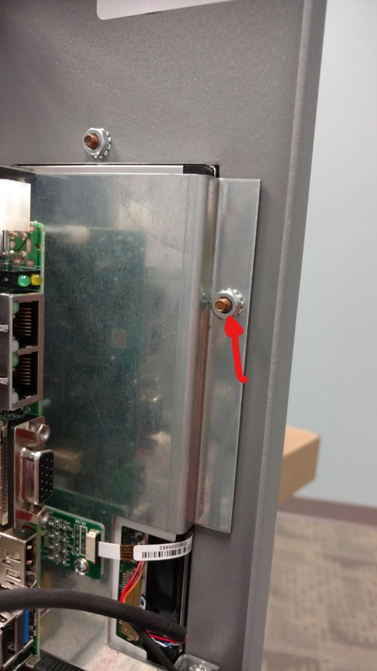
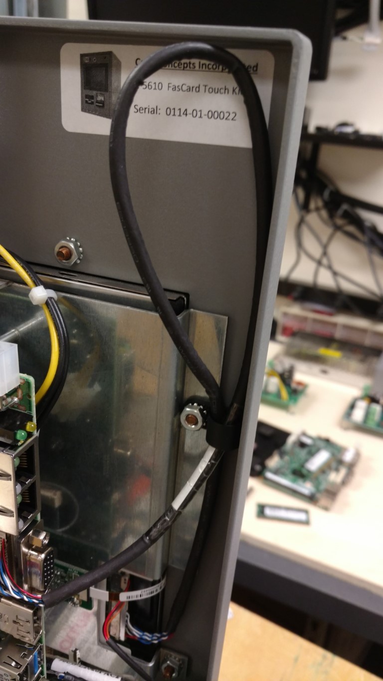
Use the plastic C-Clamp to secure the video cable to the monitor mounting bolt as shown below.
Make sure to leave enough loose slack but also make sure that the cable will not be damaged during closing of the drawer:
Take the existing video cable and push behind the motherboard to move it out of the way.
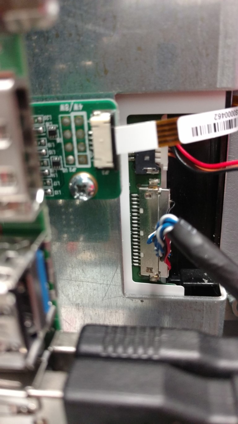
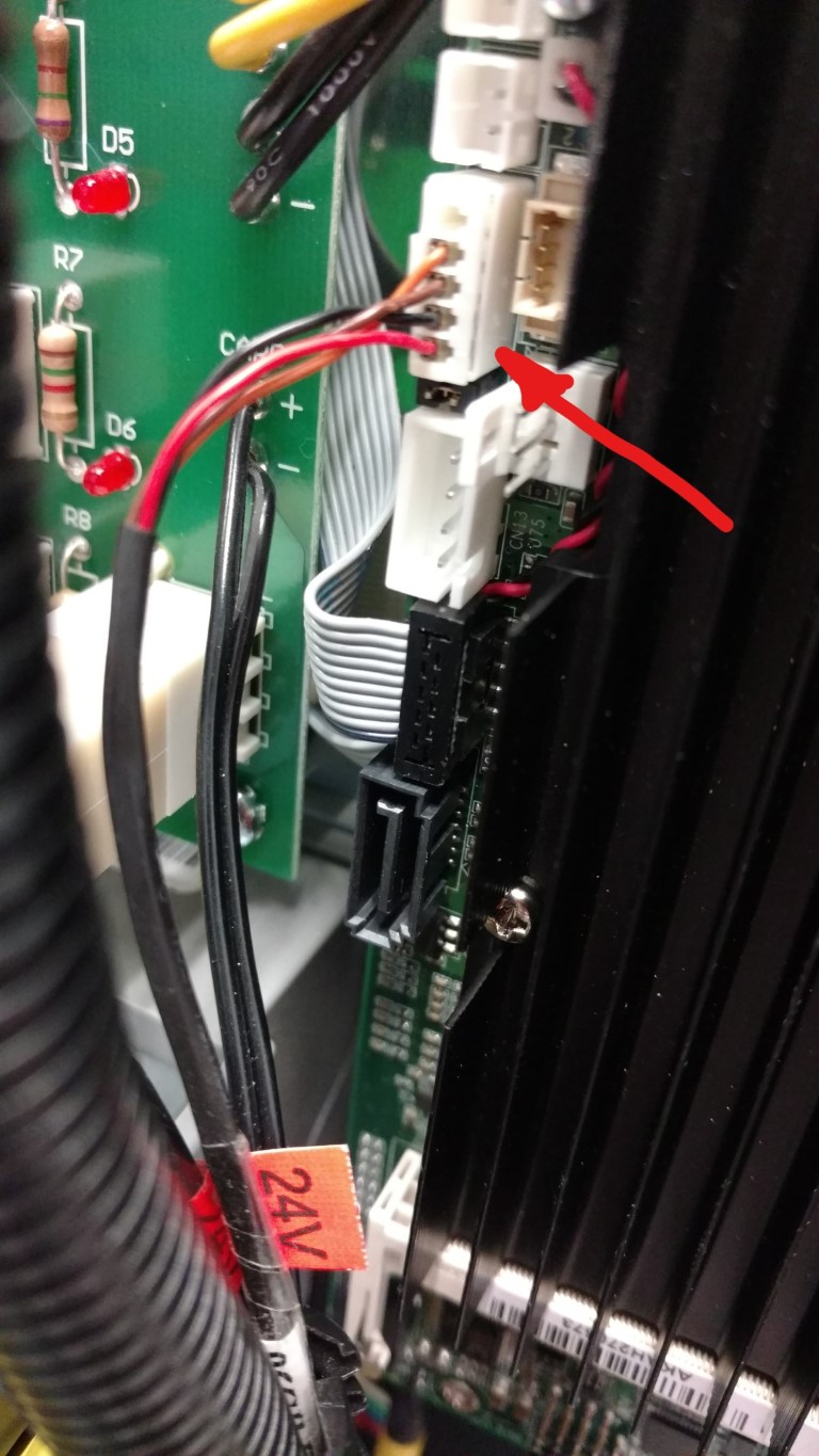
Insert the grey power control board harness in the plug located on the left side of the motherboard.
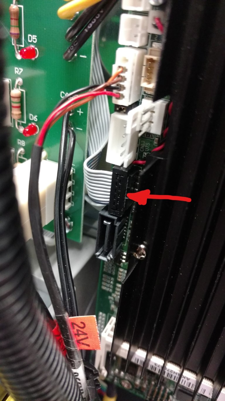
Insert the monitor power cable (orange brown red and black wires) in the slot indicated below.
Power on the Kiosk and test for functionality
Tips & Warnings
- Power off the Kiosk before beginning any work.
- Ground your body before touching the static sensitive equipment.