FasCard Touch Kiosk Grounding Kit Installation Guide
This guide is intended to instruct the installer on how to safely install the FasCard Touch Kiosk Grounding Kit.
At any point, feel free to contact CCI Technical Support for any issues, concerns, or questions that may come up. You can reach them immediately by calling 630-930-5115, option 2. You can also reach them by email at support@laundrycard.com.Contact us!
Required parts & tools
Screw 8-32" x 3/8" - Kep Screw - Build: T/AVK 8-32" x 1/2" - Zinc Cable Clamp - Build: TK 1/4" Cable Clamp - Build: AVK 1/2", 3/8" width - Blk Nylon Kiosk Harness - Build: TK For C-5610 Cabinet Touch Kiosk Hrns- Build: TKH For C-5610R1 Cabinet
Part ID Description Image C-1063

C-1079

C-1081-M

C-1083

C-5666R1

C-5666R2

- 2-point harness (included in C-5666R1)
- 4-point harness (included in C-5666R1)
- P1 3" Philips head screwdriver (not included)
- P2 4" Philips head screwdriver (not included)
- 11/32" Wrench or nut driver (not included)
Step-by-step guide
Disconnect any electrical device from power before performing any work on the device. It is recommended that the instructions contained herein be performed by individuals who are qualified to perform these tasks. Card Concepts Inc. takes no responsibility for the accuracy of this document or any damage that may occur to target equipment. Technical Support recommends using all appropriate safety equipment (such as hand and eye protection) during execution of the instructions below.
Step 1 - Powering down the Touch Kiosk
- Open the front of the Touch Kiosk and plug-in the keyboard in any available USB port on the main CPU board.
- Press CTRL+ALT+DELETE to bring up the Windows Task menu.
- Touch the power icon in the lower right-hand corner of the screen.
- Select the SHUTDOWN option from the new menu.
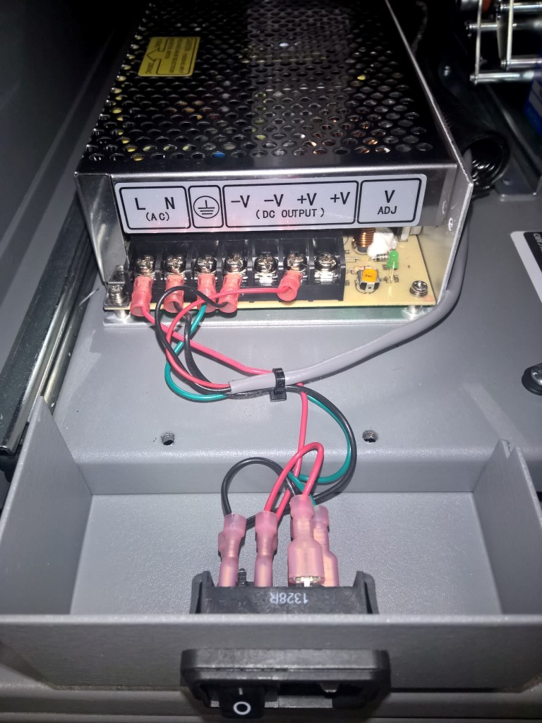
- Flip the rocker switch so that the "O" is depressed.
Step 2 - Connecting the rear of the Kiosk
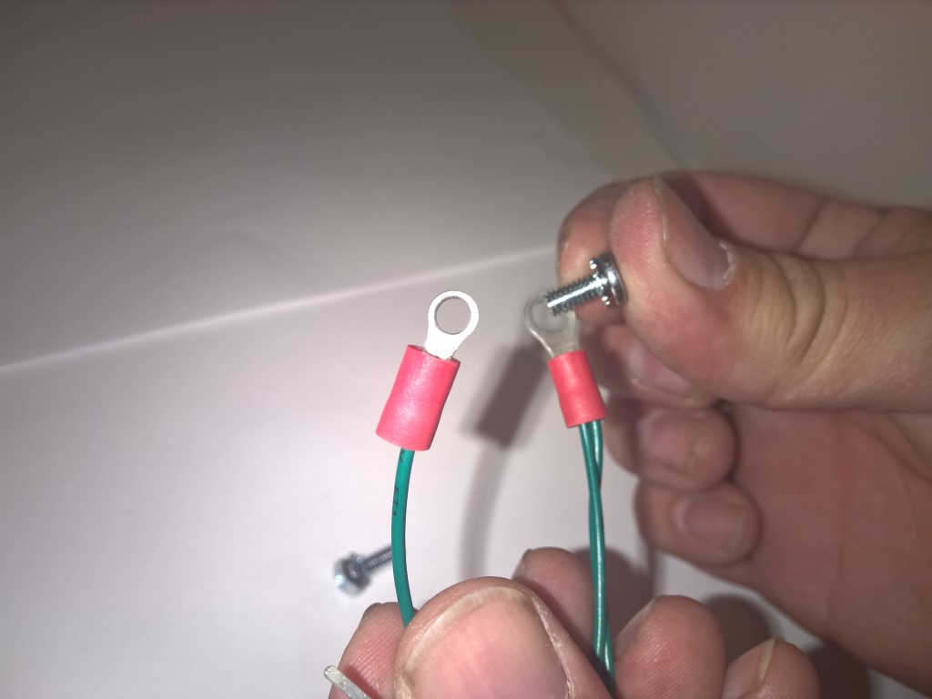
- Locate the shorter screw (P/N: C-1063) and smaller Metal Clamp (P/N: C-1081-M).
- Insert the C-1063 screw into the larger ring on the 4-point harness.
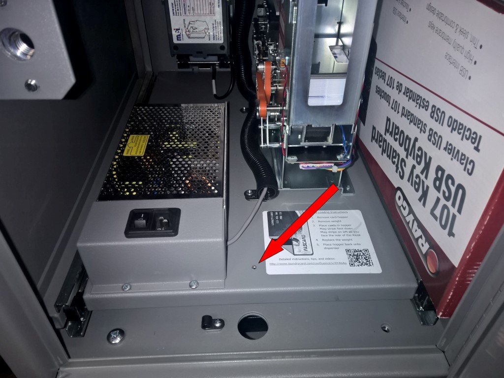
- Bend the C-1081-M clamp around the existing power cable, about 10" from the Kiosk end.
- This provides strain relief for the cable.
- Insert the C-1063 screw and 4-point harness through the clamp and secure it to the base of the drawer as shown here:
The end result should look like the following:
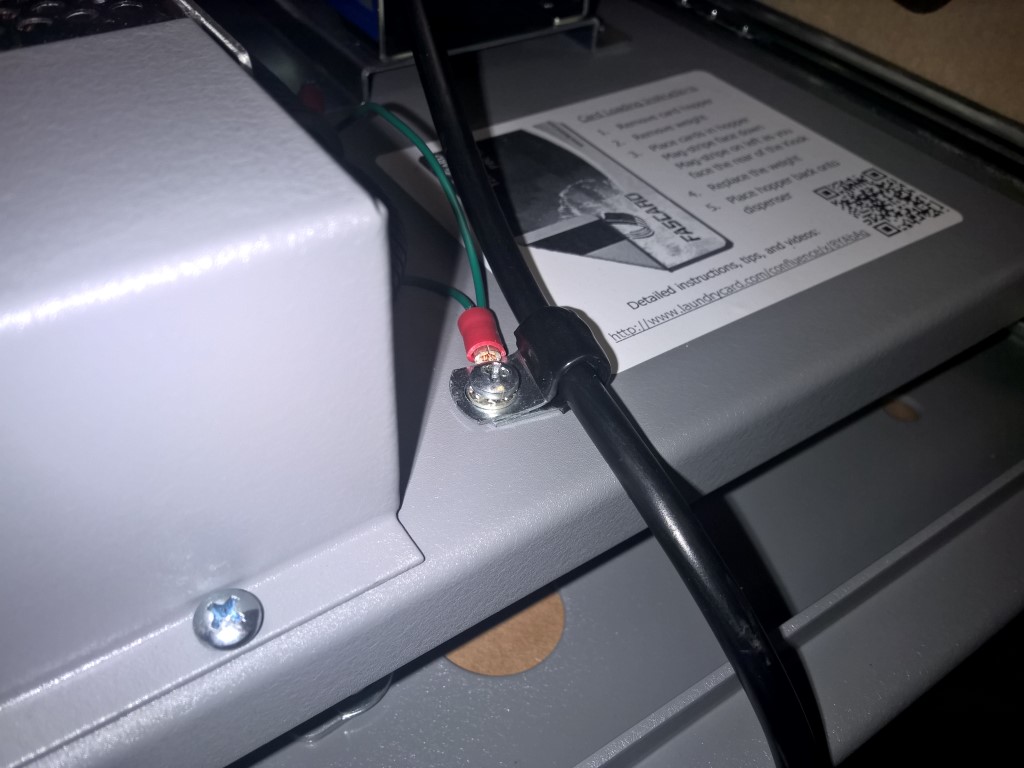
There may be an existing plastic wire clamp and screw, you can discard these.
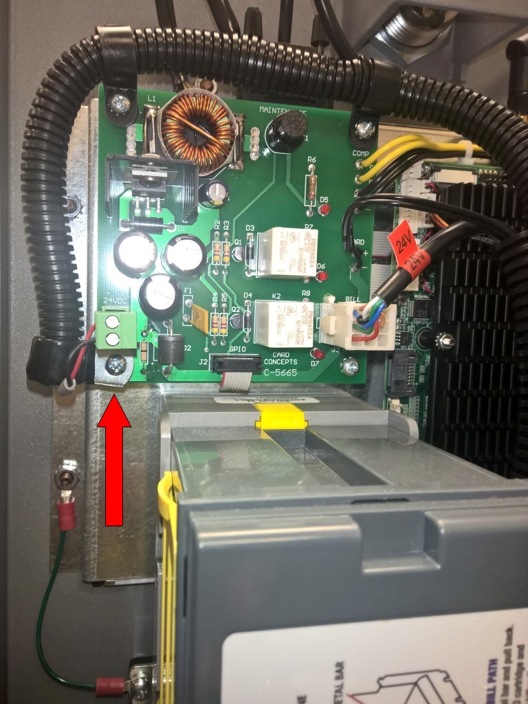
Step 3 – Securing the grounding screws
- Using a P2 Philips screwdriver, remove the two (2) screws securing the power supply protector cover. Pull away towards you when removing.
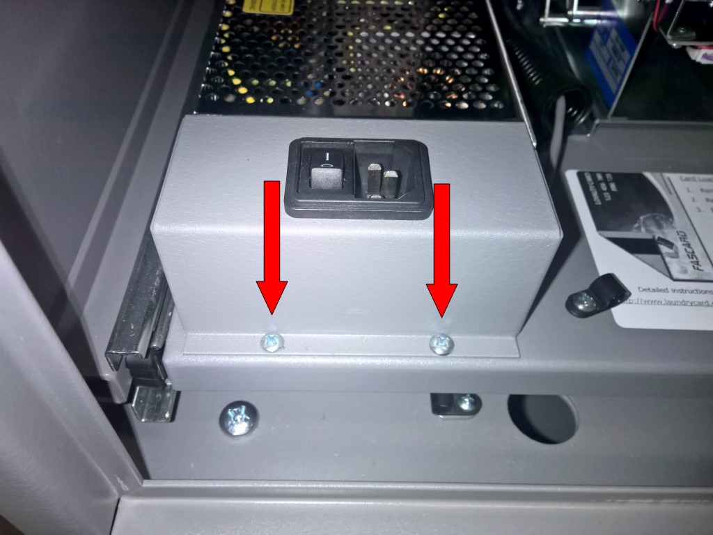
- Be cautious when opening the protective cover so as to avoid pulling or breaking wire connections between the cover and Power Supply Unit (PSU).
- Loosen the screws on the PSU marked with the
 symbol (for green wire) and -V (for black wire).
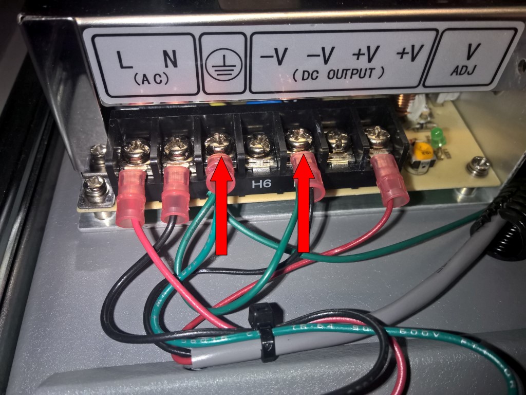
- Insert the forked ends of the 4-point harness into the loosened terminals.
- Tighten the terminals and replace the power supply cover, taking care not to pinch any wires.
- There is a notch out of the corner to allow the wires to come out of the cover.
- Replace the two (2) screws and tighten down the power supply cover.
- Using a P1 Philips screwdriver, remove the screw from the base of the card dispenser closest to the power supply.
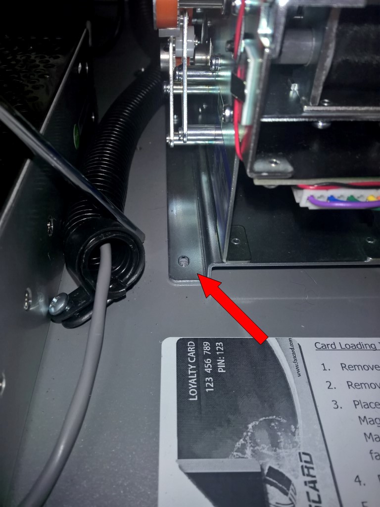
- Insert the screw through the remaining small ring on the 4-point harness.
- Re-secure the screw back to the dispenser base.
Step 4 – Grounding the main CPU board
- Locate the Power Control Board (PCB) on the back of the front panel.
- Remove the screw in the lower left-hand corner that is securing a plastic clamp.
- Remove and discard the plastic clamp and replace it with the C-1083-M clamp, binding it to the end of the black looming.
- Re-secure the clamp to the board with the screw that was removed earlier.
Step 5 – Grounding the Bill Note Acceptor (BNA)
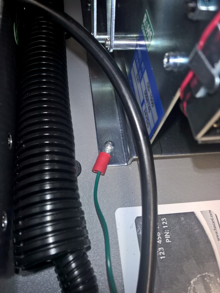
- Remove the lower 11/32" nut on the left side of the assembly bracket.
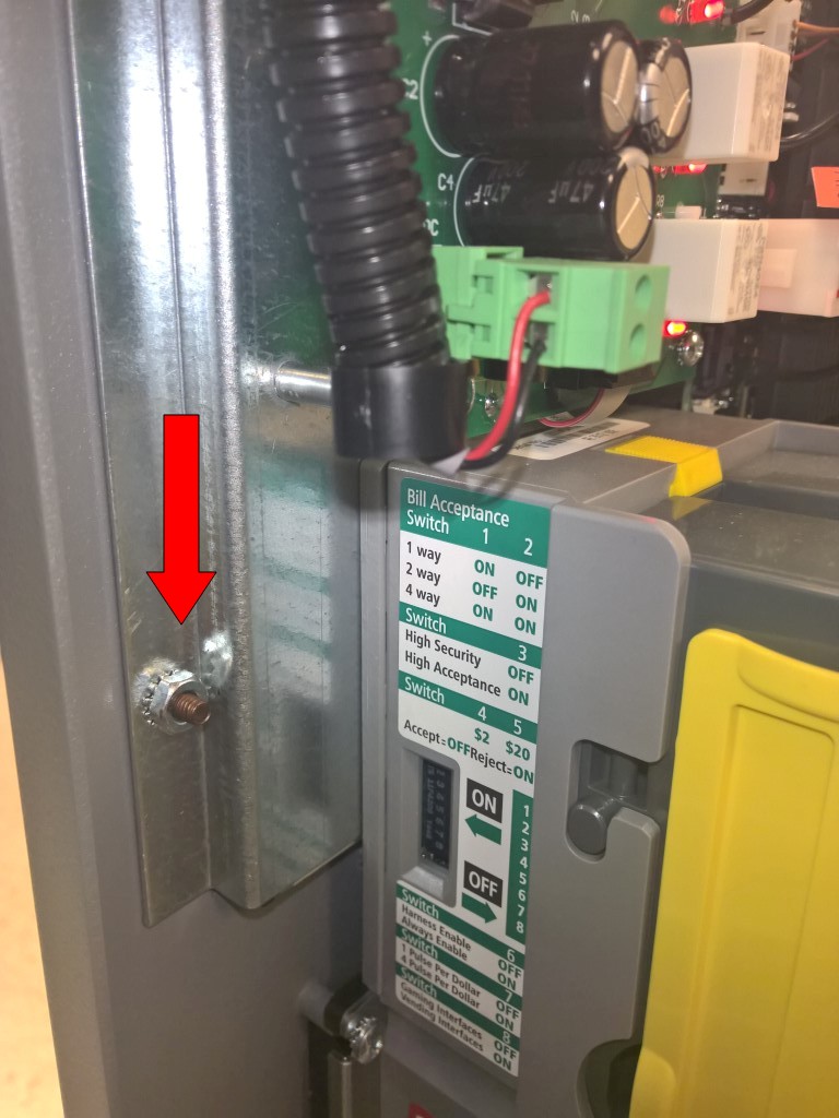
- Put one end of the 2-point harness on the stud and re-secured the nut to the stud.
- Remove the upper-left screw from the BNA and apply the remaining end of the 2-point, re-securing it with the C-1063 screw.
Step 6 – Powering on and closing the Touch Kiosk
- Plug-in the power cord to the power supply.
- Power on the Touch Kiosk by flipping the rocker switch so the "I" is depressed.
- Push the Kiosk drawer closed and lock it.
Related documentation